An electronic multiplexer makes it possible for several signals to share one device or resource, for example one A/D converter or one communication line, instead of having one device per input signal. Sebuah Multiplexer elektronik memungkinkan beberapa sinyal untuk berbagi satu perangkat atau sumber daya, misalnya satu A / D converter atau satu jalur komunikasi, daripada harus satu perangkat per sinyal input.
On the other hand, a demultiplexer (or demux ) is a device taking a single input signal and selecting one of many data-output-lines, which is connected to the single input. Di sisi lain, demultiplexer (atau demux) adalah perangkat mengambil sinyal input tunggal dan memilih salah satu dari banyak-output data-baris, yang dihubungkan ke input tunggal. A multiplexer is often used with a complementary demultiplexer on the receiving end. [ 1 ] Multiplexer Sebuah sering digunakan dengan demultiplexer pelengkap di ujung penerima. [1]
An electronic multiplexer can be considered as a multiple-input, single-output switch, and a demultiplexer as a single-input, multiple-output switch. [ 3 ] The schematic symbol for a multiplexer is an isosceles trapezoid with the longer parallel side containing the input pins and the short parallel side containing the output pin. [ 4 ] The schematic on the right shows a 2-to-1 multiplexer on the left and an equivalent switch on the right. Sebuah Multiplexer elektronik dapat dianggap sebagai beberapa masukan-tunggal-output switch, dan demultiplexer sebagai masukan-tunggal, ganda-output switch. [3] Simbol skematis untuk multiplexer adalah trapesium sama kaki dengan sisi sejajar lagi berisi pin input dan sisi paralel pendek berisi pin output. [4] Skema di sebelah kanan menunjukkan multiplexer 2-ke-1 di kiri dan saklar setara di sebelah kanan. The s e l wire connects the desired input to the output. S e l kawat menghubungkan input yang diinginkan untuk output.


Satu digunakan untuk multiplexer adalah penghematan biaya dengan menghubungkan multiplexer dan demultiplexer (atau demux) bersama-sama melalui saluran tunggal (dengan menghubungkan output tunggal multiplexer untuk masukan tunggal demultiplexer itu). The image to the right demonstrates this. Gambar ke kanan menunjukkan hal ini. In this case, the cost of implementing separate channels for each data source is more expensive than the cost and inconvenience of providing the multiplexing/demultiplexing functions. Dalam hal ini, biaya pelaksanaan saluran terpisah untuk setiap sumber data yang lebih mahal daripada biaya dan ketidaknyamanan menyediakan fungsi multiplexing / demultiplexing. In a physical analogy , consider the merging behaviour of commuters crossing a narrow bridge; vehicles will take turns using the few available lanes. Dalam sebuah fisik analogi , mempertimbangkan perilaku penggabungan penumpang menyeberangi jembatan sempit, kendaraan akan bergiliran menggunakan jalur yang tersedia sedikit. Upon reaching the end of the bridge they will separate into separate routes to their destinations. Setelah mencapai ujung jembatan mereka akan terpisah menjadi rute terpisah untuk tujuan mereka. At the receiving end of the data link a complementary demultiplexer is normally required to break single data stream back down into the original streams. Pada akhir penerimaan dari data link demultiplexer pelengkap biasanya diperlukan untuk memecah aliran data tunggal kembali ke dalam sungai asli. In some cases, the far end system may have more functionality than a simple demultiplexer and so, while the demultiplexing still exists logically, it may never actually happen physically. Dalam beberapa kasus, sistem ujung mungkin memiliki fungsi lebih dari demultiplexer sederhana dan begitu, sementara demultiplexing masih ada secara logis, itu mungkin tidak pernah benar-benar terjadi secara fisik. This would be typical where a multiplexer serves a number of IP network users and then feeds directly into a router which immediately reads the content of the entire link into its routing processor and then does the demultiplexing in memory from where it will be converted directly into IP packets. Ini akan menjadi khas di mana multiplexer melayani sejumlah IP pengguna jaringan dan kemudian feed langsung ke router yang langsung membaca isi dari link tersebut ke dalam nya rute prosesor dan kemudian melakukan demultiplexing dalam memori dari mana ia akan dikonversi langsung ke IP paket.
Often, a multiplexer and demultiplexer are combined together into a single piece of equipment, which is usually referred to simply as a "multiplexer". Seringkali, multiplexer dan demultiplexer digabungkan bersama menjadi satu bagian dari peralatan, yang biasanya disebut hanya sebagai "multiplexer". Both pieces of equipment are needed at both ends of a transmission link because most communications systems transmit in both directions . Kedua potongan peralatan yang diperlukan pada kedua ujung sebuah link transmisi karena kebanyakan sistem komunikasi mengirimkan di kedua arah .
A real world example is the creation of telemetry for transmission from the computer/instrumentation system of a satellite , space craft or other remote vehicle to a ground-based system. Sebuah contoh dunia nyata adalah penciptaan telemetri untuk transmisi dari sistem komputer / instrumentasi dari satelit , pesawat ruang angkasa atau kendaraan remote lain untuk sistem darat.
In analog circuit design, a multiplexer is a special type of analog switch that connects one signal selected from several inputs to a single output. Di sirkuit analog desain, multiplexer adalah tipe khusus dari saklar analog yang menghubungkan satu sinyal dipilih dari beberapa input output tunggal.
Digital multiplexers Digital multiplexer
In digital circuit design, the selector wires are of digital value. Dalam sirkuit digital desain, kabel pemilih adalah dari nilai digital. In the case of a 2-to-1 multiplexer, a logic value of 0 would connect Dalam kasus multiplexer 2-ke-1, nilai logika 0 akan menghubungkan to the output while a logic value of 1 would connect ke output sementara nilai logika 1 akan menghubungkan
  to the output. ke output. In larger multiplexers, the number of selector pins is equal to Dalam multiplexer yang lebih besar, jumlah pemilih pin adalah sama dengan
  where mana
  is the number of inputs. adalah jumlah input.
 For example, 9 to 16 inputs would require no fewer than 4 selector pins and 17 to 32 inputs would require no fewer than 5 selector pins. Sebagai contoh, 9 sampai 16 masukan akan membutuhkan tidak kurang dari 4 pin pemilih dan 17-32 input akan membutuhkan tidak kurang dari 5 pin pemilih. The binary value expressed on these selector pins determines the selected input pin. Nilai biner diekspresikan pada pin ini pemilih menentukan pin input yang dipilih.
A 2-to-1 multiplexer has a boolean equation where Sebuah multiplexer 2-ke-1 memiliki persamaan boolean mana
 and dan
  are the two inputs, adalah dua masukan,
  is the selector input, and adalah input pemilih, dan
  is the output: adalah output:

| | | |
| 0 0 | 1 1 | 1 1 | 1 1 |
| 1 1 | 0 0 | 1 1 | |
| 0 0 | 1 1 | 0 0 | |
| 0 0 | 0 0 | 0 0 | |
| 1 1 | 1 1 | 1 1 | 1 1 |
| 1 1 | 0 0 | 0 0 | |
| 0 0 | 1 1 | 1 1 | |
| 0 0 | 0 0 | 0 0 |
 then kemudian
  but when tetapi ketika
  then kemudian
  . . A straightforward realization of this 2-to-1 multiplexer would need 2 AND gates, an OR gate, and a NOT gate. Sebuah realisasi langsung dari multiplexer 2-ke-1 akan membutuhkan 2 gerbang AND, gerbang OR, gerbang NOT dan.
 Larger multiplexers are also common and, as stated above, require Multiplexer yang lebih besar juga umum dan, seperti disebutkan di atas, memerlukan
selector pins for n inputs. pemilih pin untuk input n. Other common sizes are 4-to-1, 8-to-1, and 16-to-1. Ukuran umum lainnya adalah 4-ke-1, 8-ke-1, dan 16-ke-1. Since digital logic uses binary values, powers of 2 are used (4, 8, 16) to maximally control a number of inputs for the given number of selector inputs. Karena logika digital menggunakan nilai biner, pangkat 2 yang digunakan (4, 8, 16) untuk maksimal mengontrol sejumlah masukan untuk jumlah input yang diberikan pemilih.  4-to-1 mux 4-ke-1 mux
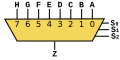 8-to-1 mux 8-ke-1 mux
 16-to-1 mux 16-ke-1 mux


| ||||


Chaining multiplexers multiplexer Chaining
Larger multiplexers can be constructed by using smaller multiplexers by chaining them together. Multiplexer lebih besar dapat dibangun dengan menggunakan multiplexer yang lebih kecil oleh chaining mereka bersama-sama. For example, an 8-to-1 multiplexer can be made with two 4-to-1 and one 2-to-1 multiplexers. Sebagai contoh, sebuah multiplexer 8-ke-1 dapat dibuat dengan dua 4-ke-1 dan satu 2-ke-1 multiplexer. The two 4-to-1 multiplexer outputs are fed into the 2-to-1 with the selector pins on the 4-to-1's put in parallel giving a total number of selector inputs to 3, which is equivalent to an 8-to-1. Dua 4-ke-1 output multiplexer yang dimasukkan ke dalam 2-ke-1 dengan pin pemilih pada 4-ke-1 yang dimasukkan ke dalam paralel memberikan jumlah masukan pemilih untuk 3, yang setara dengan sebuah 8-untuk -1.[ edit ] List of ICs which provide multiplexing [ sunting ] Daftar IC yang menyediakan multiplexing
The 7400 series has several ICs that contain multiplexer(s): Para seri 7400 memiliki beberapa IC yang mengandung multiplexer (s):| S.No. S.No. | IC No. IC No | Function Fungsi | Output State Keluaran Negara |
|---|---|---|---|
| 1 1 | 74157 74157 | Quad 2:1 mux. Quad mux 2:1. | Output same as input given Sama dengan input output yang diberikan |
| 2 2 | 74158 74158 | Quad 2:1 mux. Quad mux 2:1. | Output is inverted input Output terbalik masukan |
| 3 3 | 74153 74153 | Dual 4:1 mux. Ganda 04:01 mux. | Output same as input Sama dengan input output yang |
| 4 4 | 74352 74352 | Dual 4:1 mux. Ganda 04:01 mux. | Output is inverted input Output terbalik masukan |
| 5 5 | 74151A 74151A | 8:1 mux. Mux 8:1. | Both outputs available (ie, complementary outputs) Kedua output yang tersedia (yaitu, output pelengkap) |
| 6 6 | 74151 74151 | 8:1 mux. Mux 8:1. | Output is inverted input Output terbalik masukan |
| 7 7 | 74150 74150 | 16:1 mux. Mux 16:01. | Output is inverted input Output terbalik masukan |
[ edit ] Digital demultiplexers [ sunting ] Digital demultiplexers
Demultiplexers take one data input and a number of selection inputs, and they have several outputs. Demultiplexers mengambil satu masukan data dan jumlah input seleksi, dan mereka memiliki beberapa output. They forward the data input to one of the outputs depending on the values of the selection inputs. Mereka meneruskan input data ke salah satu output tergantung pada nilai-nilai dari input seleksi. Demultiplexers are sometimes convenient for designing general purpose logic, because if the demultiplexer's input is always true, the demultiplexer acts as a decoder . Demultiplexers kadang-kadang nyaman untuk merancang logika tujuan umum, karena jika input demultiplexer adalah selalu benar, demultiplexer bertindak sebagai decoder . This means that any function of the selection bits can be constructed by logically OR-ing the correct set of outputs. Ini berarti bahwa setiap fungsi dari bit seleksi dapat dibangun dengan logika OR-ing set output yang benar.
List of ICs which provide demultiplexing Daftar IC yang menyediakan demultiplexing
The 7400 series has several ICs that contain demultiplexer(s): Para seri 7400 memiliki beberapa IC yang mengandung demultiplexer (s):| S.No. S.No. | IC No. (7400) IC No (7400) | IC No. (4000) IC No (4000) | Function Fungsi | Output State Keluaran Negara |
|---|---|---|---|---|
| 1 1 | 74139 74139 | Dual 1:4 demux. Ganda 01:04 demux. | Output is inverted input Output terbalik masukan | |
| 3 3 | 74156 74156 | Dual 1:4 demux. Ganda 01:04 demux. | Output is open collector Output kolektor terbuka | |
| 4 4 | 74138 74138 | 1:8 demux. 01:08 demux. | Output is inverted input Output terbalik masukan | |
| 5 5 | 74238 74238 | 1:8 demux. 01:08 demux. | Output is same as input Output yang sama sebagai masukan | |
| 6 6 | 74154 74154 | 1:16 demux. 1:16 demux. | Output is inverted input Output terbalik masukan | |
| 7 7 | 74159 74159 | CD4514/15 CD4514/15 | 1:16 demux. 1:16 demux. | Output is open collector and same as input Output kolektor terbuka dan sama sebagai masukan |
Multiplexers as PLDs Multiplekser sebagai PLDs
Multiplexers can also be used as programmable logic devices. Multiplexer juga dapat digunakan sebagai perangkat programmable logic. By specifying the logic arrangement in the input signals, a custom logic circuit can be created. Dengan menetapkan susunan logika dalam sinyal input, rangkaian logika kustom dapat dibuat. The selector inputs then act as the logic inputs. Masukan pemilih kemudian bertindak sebagai input logika. This is especially useful in situations when cost is a factor and for modularity. Hal ini sangat berguna dalam situasi ketika biaya merupakan faktor dan untuk modularitas.Sumber:ditulis oleh wikipidea